Designing 3-Story Enterprise Campus Network with Cisco
Daftar Isi
- 🛠️ Feature Summary & Architecture Specifications
- 🗺️ Network Topology & Architecture
- 📊 IP Addressing Scheme (Addressing Table)
- 💻 Core Configuration Snippets (Cisco IOS)
- 1. Inter-VLAN Routing Setup on Core Multilayer Switch (Core-MLS)
- 2. Multi-Area OSPF Dynamic Routing Configuration
- 🧪 Laboratory Verification & Testing Results
- 🔍 Architecture Troubleshooting & Fixes
- Problem 1: Floor 3 Workstations Failing to Acquire Centralized DHCP Leases
- Problem 2: OSPF Neighbor Adjacency Stuck in EXSTART/EXCHANGE State
- 💬 Discussion & Community Input
Designing medium-to-enterprise scale network infrastructures demands strict broadcast domain separation, efficient packet routing, and fault-tolerant redundancy. This article explores a simulated 3-story corporate campus network architecture built in Cisco Packet Tracer, integrating Inter-VLAN Routing on a Core Multilayer Switch (MLS), Multi-Area OSPF dynamic routing, and centralized IP assignment.
🛠️ Feature Summary & Architecture Specifications
This infrastructure handles inter-departmental traffic segmentation across a three-floor building with the following technical design parameters:
- Simulator: Cisco Packet Tracer v8.x
- Dynamic Routing Protocol: Multi-Area OSPF (Area 0 Backbone & Area 1 Branch)
- Network Segmentation: Inter-VLAN Routing (VLAN 10, VLAN 20, VLAN 30) on Core Multilayer Switch
- Centralized IP Services: DHCP Server & DHCP Relay Agent (
ip helper-address) - Security & Traffic Filtering: Standard & Extended Access Control Lists (ACLs)
🗺️ Network Topology & Architecture
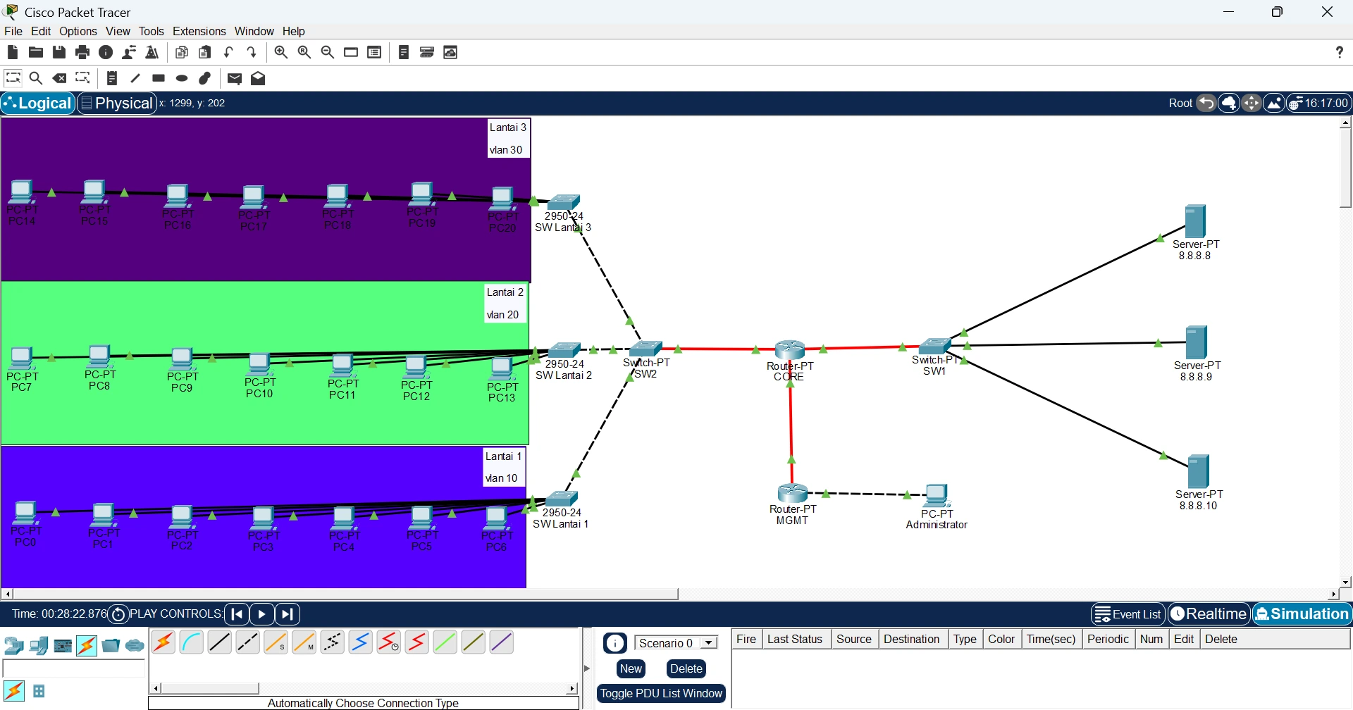 Figure 1: 3-story enterprise campus network topology diagram in Cisco Packet Tracer (VLAN 10, 20, 30, Multi-Area OSPF, Core Switch, and Server).
📊 IP Addressing Scheme (Addressing Table)
The table below outlines IP subnet allocations and OSPF area assignments across all primary core devices:
| Device | Interface | VLAN ID | IP Address | Subnet Mask | OSPF Area | Location Description |
|---|---|---|---|---|---|---|
Core-MLS | Sub-int / Sw | VLAN 10 | 192.168.10.1 | 255.255.255.0 | Area 0 | Floor 1 (Staff/Dev) |
Core-MLS | Sub-int / Sw | VLAN 20 | 192.168.20.1 | 255.255.255.0 | Area 0 | Floor 2 (Finance/HR) |
Core-MLS | Sub-int / Sw | VLAN 30 | 192.168.30.1 | 255.255.255.0 | Area 1 | Floor 3 (Executive/Server) |
Router-A | Gig0/0 | - | 10.10.10.1 | 255.255.255.252 | Area 0 | Core Uplink Backbone |
Router-B | Gig0/1 | - | 10.10.10.2 | 255.255.255.252 | Area 1 | Inter-Area Branch Uplink |
💻 Core Configuration Snippets (Cisco IOS)
1. Inter-VLAN Routing Setup on Core Multilayer Switch (Core-MLS)
Defining Virtual LANs and enabling Layer 3 IP routing capabilities on the switch core:
vlan 10
 name Floor-1
vlan 20
 name Floor-2
vlan 30
 name Floor-3
exit

! Enable Layer 3 IP Routing Engine
ip routing

interface vlan 10
 ip address 192.168.10.1 255.255.255.0
 no shutdown

interface vlan 20
 ip address 192.168.20.1 255.255.255.0
 no shutdown

interface vlan 30
 ip address 192.168.30.1 255.255.255.0
 no shutdown
2. Multi-Area OSPF Dynamic Routing Configuration
Configuring dynamic route propagation between Area 0 backbone networks and Area 1 branch networks:
router ospf 1
 router-id 1.1.1.1
 network 192.168.10.0 0.0.0.255 area 0
 network 192.168.20.0 0.0.0.255 area 0
 network 10.10.10.0 0.0.0.3 area 0
 network 192.168.30.0 0.0.0.255 area 1
exit
🧪 Laboratory Verification & Testing Results
- Inter-VLAN ICMP Ping Test: All client workstations across distinct floor subnets (VLAN 10, 20, and 30) achieved 100% ICMP ping connectivity (Success Rate 5/5).
- OSPF Neighbor Adjacency Check: Executing
show ip ospf neighborconfirmedFULL/DRandFULL/BDRoperational states without packet drops. - Routing Table Inspection: Running
show ip routeverified active internal OSPF routes (O) and inter-area summary routes (O IA).
🔍 Architecture Troubleshooting & Fixes
Problem 1: Floor 3 Workstations Failing to Acquire Centralized DHCP Leases
- Issue: Client devices attached to VLAN 30 received self-assigned APIPA IP addresses (
169.254.x.x). - Analysis: Layer 2 broadcast DHCP Request packets cannot traverse inter-VLAN / Layer 3 routing boundaries.
- Solution: Configured a DHCP Relay Agent on the SVI interface for VLAN 30 using
ip helper-address [IP_DHCP_Server].
Problem 2: OSPF Neighbor Adjacency Stuck in EXSTART/EXCHANGE State
- Issue: OSPF neighbor relationship between backbone routers failed to reach the
FULLstate. - Analysis: A mismatch in Maximum Transmission Unit (MTU) sizes existed on the interconnecting physical interfaces.
- Solution: Aligned interface MTU values or injected
ip ospf mtu-ignoreon mismatched interface links.
💬 Discussion & Community Input
Are you currently designing multi-story campus network topologies or troubleshooting OSPF route exchanges in Cisco Packet Tracer? Share your ideas or questions in the comments section below!
References & Cited Sources (2)
- Cisco Networking Academy - Inter-VLAN Routing Configuration https://www.cisco.com/c/en/us/support/docs/lan-switching/inter-vlan-routing/41860-howto-itvlan.html ↗
- Cisco OSPF Design Guide & Multi-Area Architecture https://www.cisco.com/c/en/us/support/docs/ip/open-shortest-path-first-ospf/7039-1.html ↗